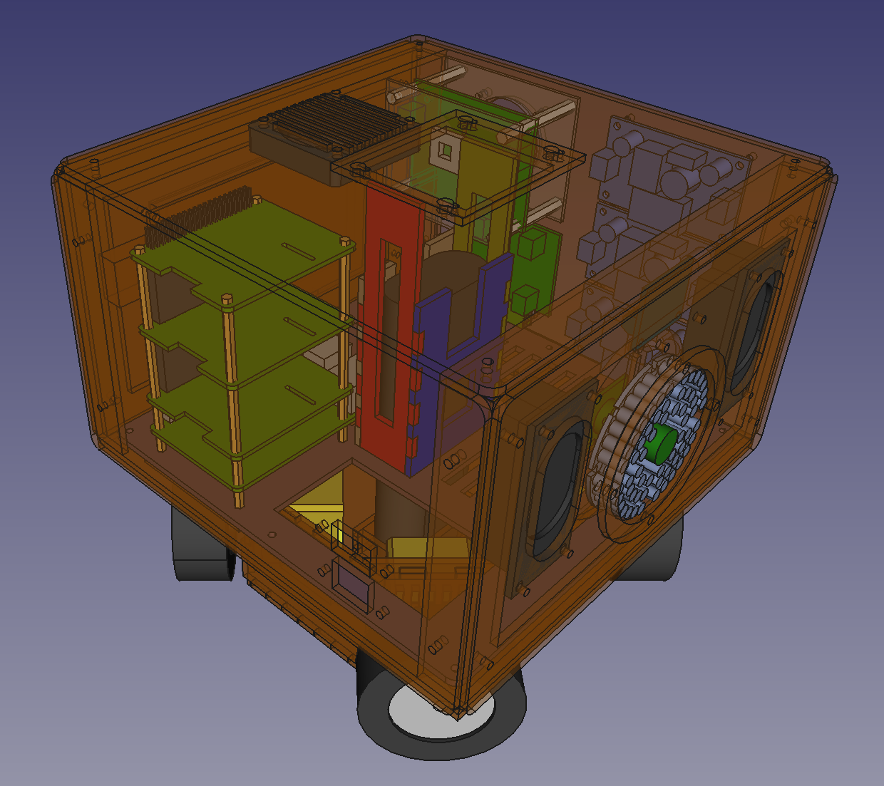
It took a couple weeks, but got a whole new design. Hit pretty much all the targets I mentioned in the previous post.
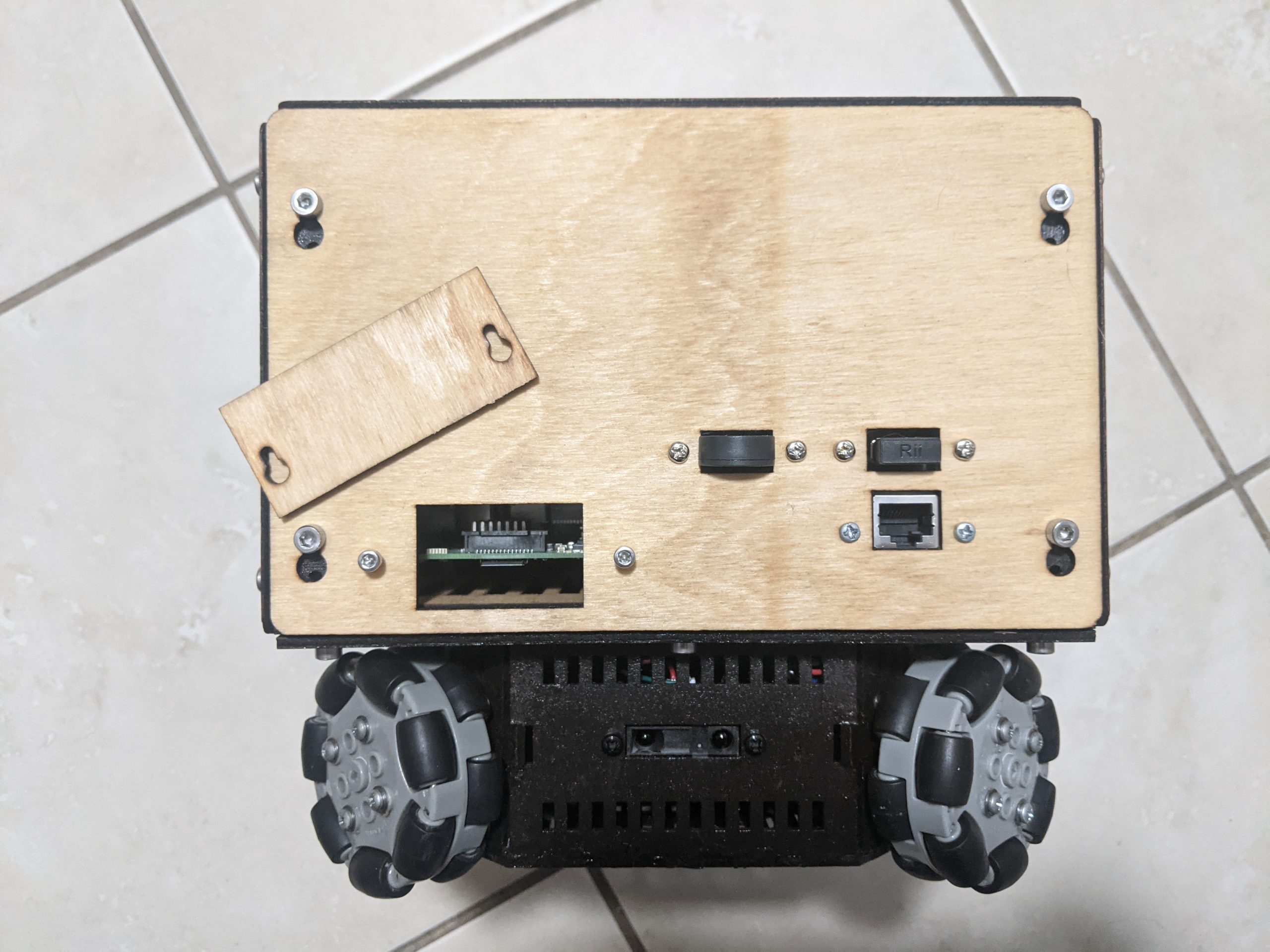
Only issue that I ran into so far is that the audio isn’t working, which sucks as that’s all on the bottom layer. The audio, range finders, and motors are all in a tangled mess in the least accessible area of the robot. Fortunately, fixing this gives me a great opportunity to do a proper tear down, showing off the design of the robot.
Currently, everything else seems to be working. I2C sees the accelerometer, gyroscope,and range finder ADC. The stepper drivers are able to lock the wheels, and make them turn. The new night vision camera’s wider FOV (130°) really helps, but I’d have preferred something closer to 160°-170°. Unfortunately, I can’t find anything in that range so this will do for now.
After the speaker repairs, it’s time to do the fun part: low level control of the motors and sensors exposed by a REST API.
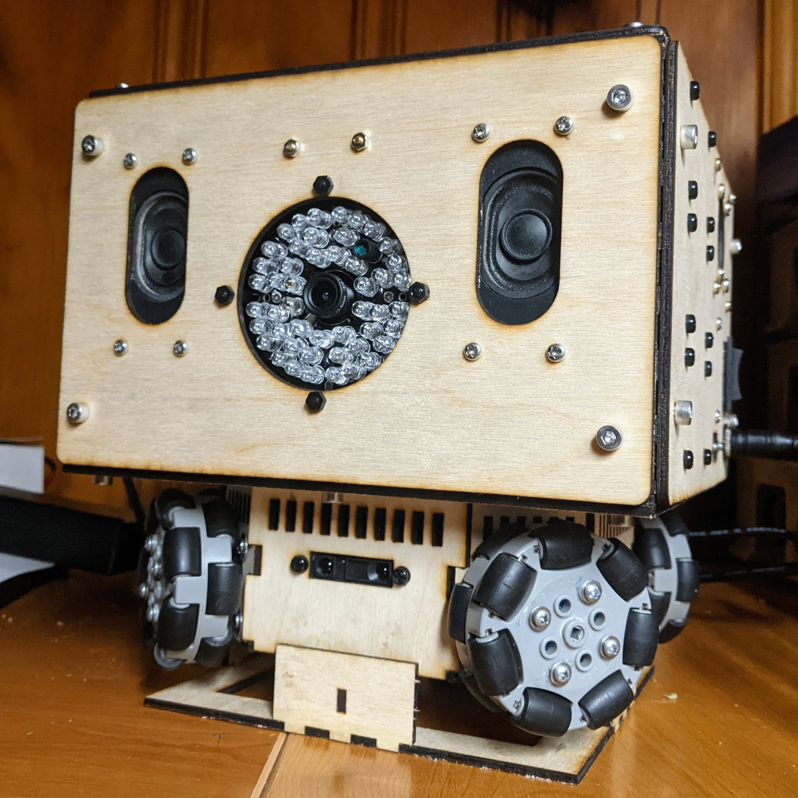
Here are some photos, in the meantime, before the coding and YouTube videos start appearing.
Murphy’s Law showed up. Back to drawing board I went.
Trouble in Paradise
After initial optimism at things seemingly coming together quickly, I then ran into 3 main problems:
The stepper motors that I had purchased were not powerful enough to move the somewhat heavy robot.
The field of view with the previous camera was too narrow, making avoiding obstacles and tracking objects more difficult.
The Magic Smoke was released from the main power regulator after a momentary short circuit while calibrating the stepper drivers’ current limitations.
V2 Changes
Problems identified, time to solve them with an updated design.
Cosmetic changes
The wood will be stained and treated to look as nice as possible
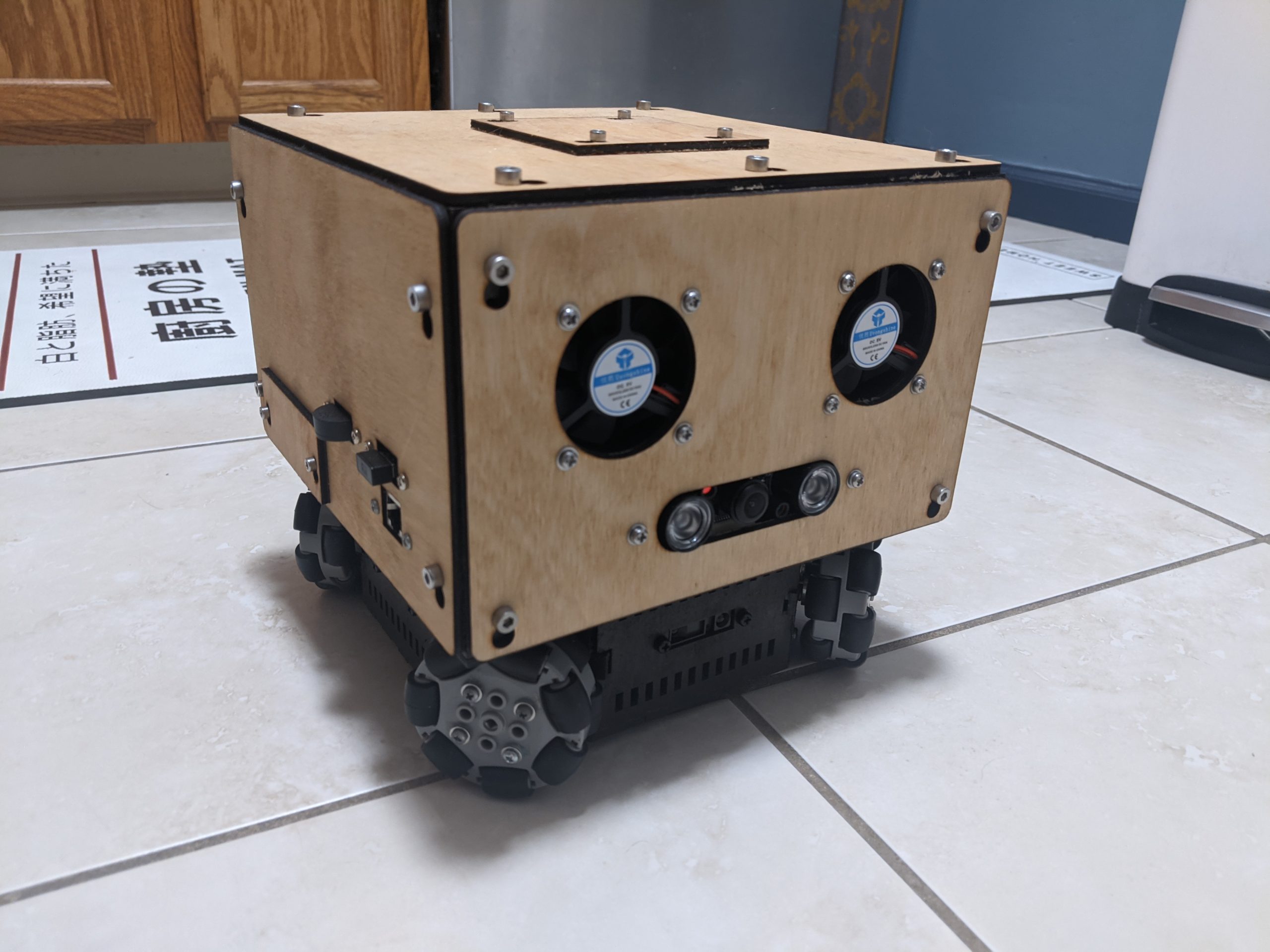
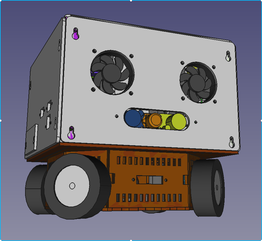
The “eyes” on the front panel will be fans now instead of speakers
Wheel enclosure
Changed to use more powerful NEMA 17 motors instead of NEMA 14
Added speaker mounts for the new smaller speakers in the front and back. The speaker in the front can be used to make the robot speak, while the speaker in the posterior will be reserved for fart sound effects.
Internal scaffolding
The internal scaffolding now has mounting holes every 10mm to increase options. Down the road, this will give me more flexibility to redesign and upgrade only parts of the robot.
All panels are designed to be easily removed by loosening them, and then sliding them a bit to take them off.
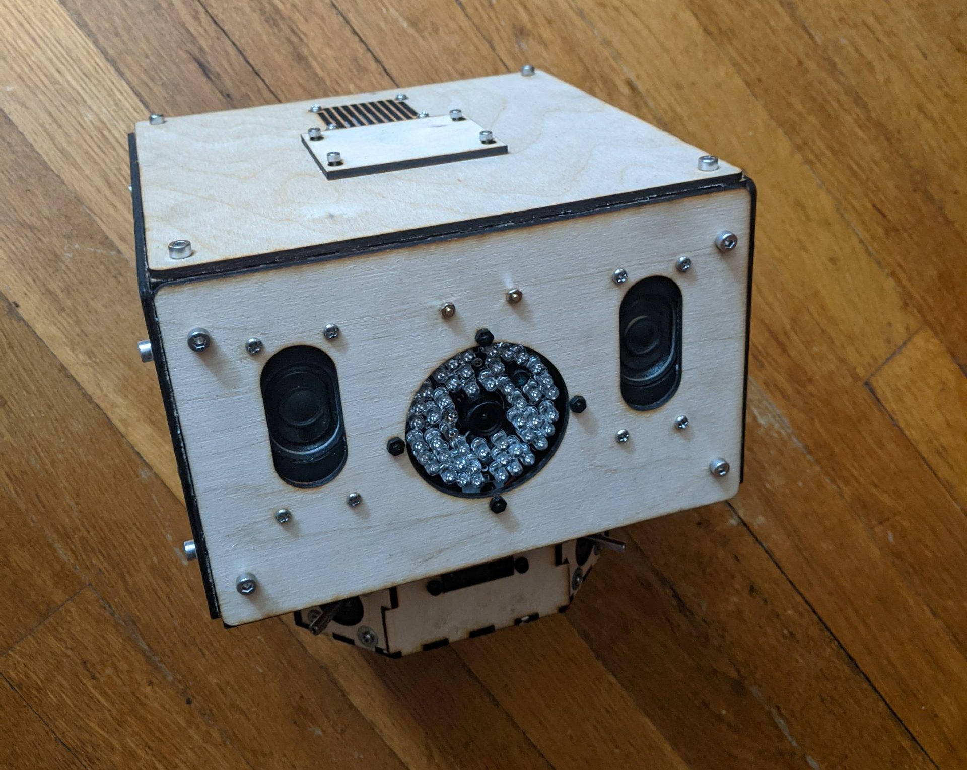
Front panel
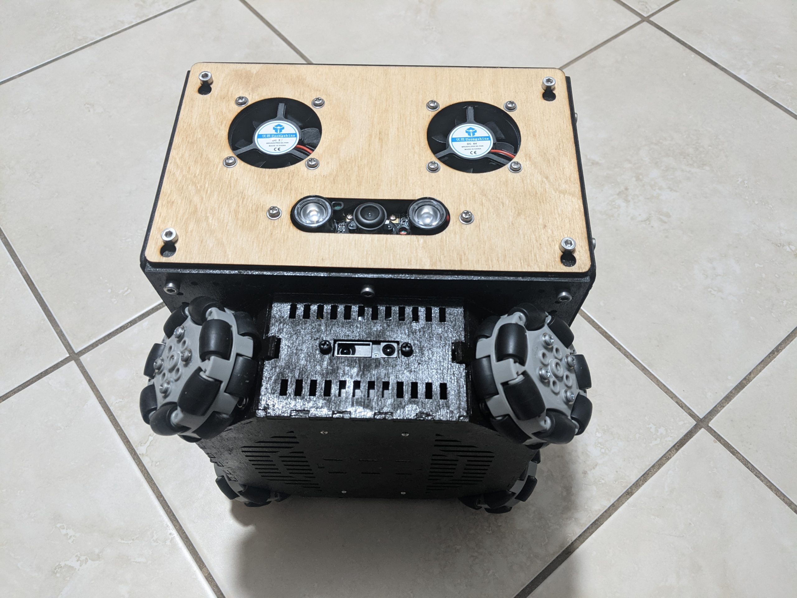
Upgraded camera to a wider field of view with smaller IR illuminators
Doubled up on the exhaust fans to avoid high CPU temperatures
Back panel
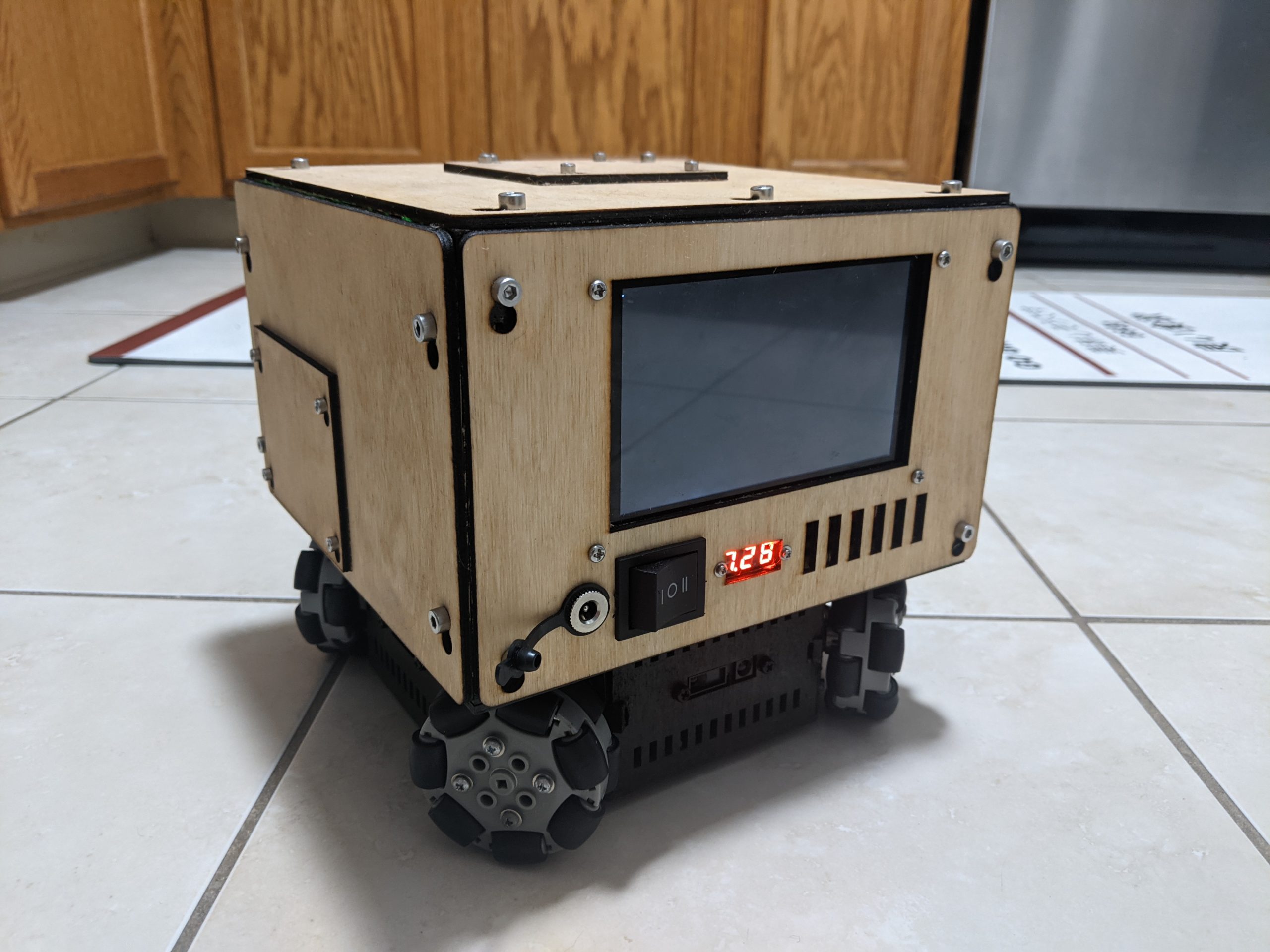
Power switch, DC In jack, and voltmeter were moved to back of the robot. I found myself spending most of my time going between the screen and the power, so I decided to put them together.
Added more ventilation in back to keep more fresh air moving over the Raspberry Pi
Left panel
Changed the orientation of the power regulators so that they face outwards. This was done to allow the entire left side to be taken off during testing and development.
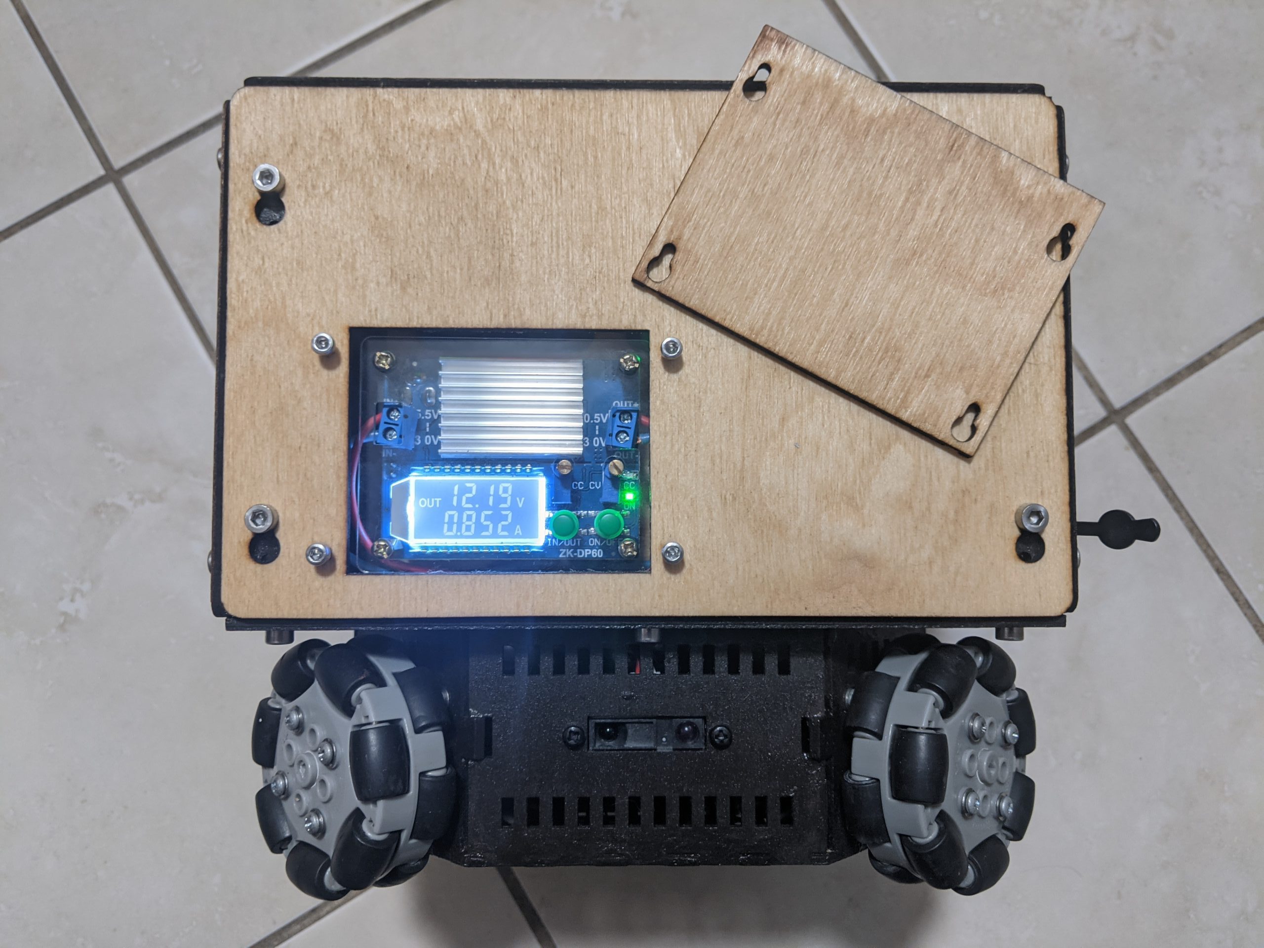
Added an access panel for only the main regulator. The main buck boost has a lot of useful power information and I’d like the option to quickly access that without removing the entire side panel.
Right panel
Added an extra USB port to allow more peripherals to be attached. It was added mostly to allow me to add a USB microphone, as it would be mostly useless if plugged directly into the Pi while inside the robot. With all the fans and motors in there, I doubt any useful audio could be captured.
Added an access panel to make it easier to swap MicroSD cards
Now that I have my robot built, it’s time to start making it do things. This is where I got stuck before last time. I was using an Arduino at the time to control the steppers and read in the range finders’ data. Now that I’m going 100% Raspberry Pi for the brain, there are no longer any memory, speed, or math concerns like last time. I expect that to be helpful.
With that history out of the way, what’s the roadmap for this next month?
Weekend 1 — The Console
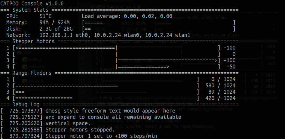
I’d like a simple console application that shows the range finders, stepper motors, and other basic status text. I’d want it expand to use all available space like htop and other similar applications. Figure it’d look something like the featured image above.
Obviously I’d color the hell out of that. After all, 95% of debugging is making sure the console colors look right. The most important part is that I have the console’s UI completely done. I don’t care if none of the sensors or motors are hooked up to it. I care about if it can store and display all the necessary state information.
I’d also want the console to be able to accept user input. I’d like it to be able to stop all the motors and put them to sleep when Escape is pressed. I’d like a way to individual control a single motor.
Weekend 2 — REST API and Movement
Once I have a way to display the internal state, I need to begin accepting REST requests to update that state. I want to focus on getting the wheels moving and performing a set routine showing off the robots maneuverability. I’d like to be able to do something like curl http://catpoo/api/dance/1 and have that trigger the robot to the first simple “dance”. Executing curl http://catpoo/api/dance/2 would do another predetermined routine.
I’ll consider this step successful once I have the following minimal API implemented:
API endpoint
Description
Notes
/api/stop
Stops all motors while keeping them energized
This is what should be called in the event I implement a panic button.
/api/sleep
Stop all motors and put them to sleep
This is also a good option for a panic button, but has the added benefit of turning off the motors. This is a good default, power-saving state.
/api/move?x=123&y=-100&rot=10
Instruct the robot to move the desired distance in the X and Y axis while rotating a certain amount
All variables are optional. /api/move would be the same as calling /api/stop. To move forward it can be called as /api/move?x=100 or the more verbose /api/move?x=100&y=0&rot=0
/api/dance/123
Cancels are current movement and begins a predetermined “dance” routine
This is how I’ll debug how well the robot is moving, or show it off when I don’t want to remote control it.
/api/status
Return status information
This would only need to include 1 or 2 things for now, but eventually would be where all the range finder and accelerometer data would be populated.
Weekend 3 — Web UI
This is where things finally start to get interesting. This weekend will all be about getting a basic website served using Bootstrap, ReactJS, and that good stuff. To keep myself from going down rabbit holes, I’ll be focusing solely on the following MVP functionality:
Video stream works
I’m not worried if there’s a bunch of lag, low FPS, or suboptimal resolution.
Video should take up the vast majority of the screen, with UI elements on top of the video
Movement controls
Doesn’t need to be fancy. If it can go forwards, backwards, stop, and turn to the left or right, that’s enough for this point
Write does notes in another post for any cool ideas for the UI. Keep this barebones as possible.
System settings page
I don’t want to make the mistake of having no options for configuring and fixing issues quickly.
At minimum, I’d like a GUI page to allow me to change the wireless network that the robot is connecting to.
A virtual keyboard would be best as I don’t want to have to rely on having the keyboard handy.
If I was going to keep the keyboard handy at all times, it would make a good remote control for debugging when w/ the console…
Weekend 4 — Typing Up Loose Ends
It’s time to pay the piper. Got to get this demo ready. To who I would be demoing, I do not know. Maybe I’ll see if it can play pool down at the local bar. Who knows.
I’ve not thought about hooking up the only simple sensors that give the robot an idea of what’s going on in the world. Anything else involves the camera which would require complicated computer vision. I’d like to go down that road, but not yet. The range finder information and accelerometer need to be represented in a visually intuitive manner on screen eventually. For now, I’d be happy with raw data dump on the side of the screen. Once I get the information flowing, I’m confident in my abilities to make it useful and look cool.
The other loose end by this point would be the webpage itself. It needs to be usable enough that my wife can use it to chase the cats. It needs to have a dead mans switch so that if the browser is closed, or the connection lost, the robot doesn’t end up crashing into the nearest wall or down a flight of steps. I also want the UI to be close to finished. Good enough for awesome night vision screenshots.
Unscheduled Tasks
Here’s the section for dumping thoughts on things that I want to do, or think I should do. I’m pretty sure they’re all option. I’m going to do them anyways.
Bill of materials
I really should collect together a list of materials that I needed to build this.
Whether someone else wants to make a copy of what I’ve done or not isn’t important.
I want to know how much it cost to build this
Write about the construction
This is where I want to explain why I did the things that I did.
I’d like to also capture the things that I was happy about, as well as the things I’d have done differently
Begin production of new body
Now that I designed everything and I know it works, I’d like to make a new chassis that looks super awesome
I’m leaning towards letting my wife do the decoration, even though I’m afraid it’ll end up looking like a panda
Once the new version is printed, it’d probably only take an hour to disassemble and reassemble in the new chassis
Future Thoughts
Once all these features are implemented, I’ll be a point where I’ll have to decide what to do next. I always wanted to develop this platform so that I could swap out the bottom and take it on a calm lake or river. How cool would it be to have a kayak buddy to help take selfies of my wife and me? Yeah, I could buy a drone off the shelf, but where’s the fun in that?
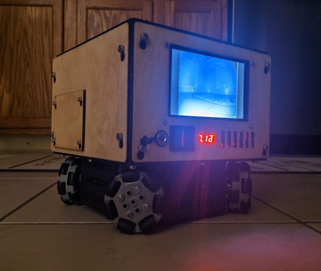
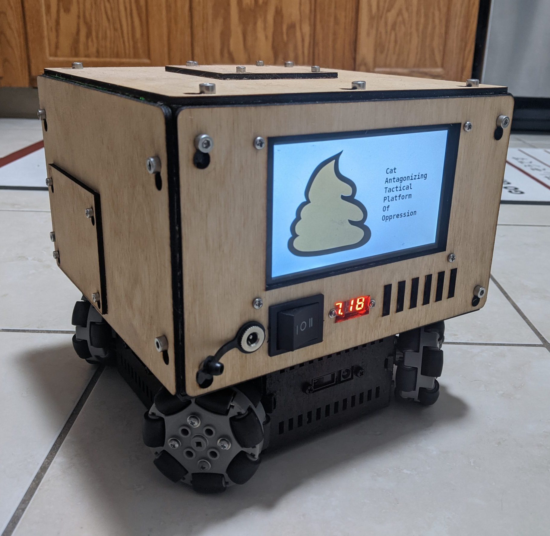
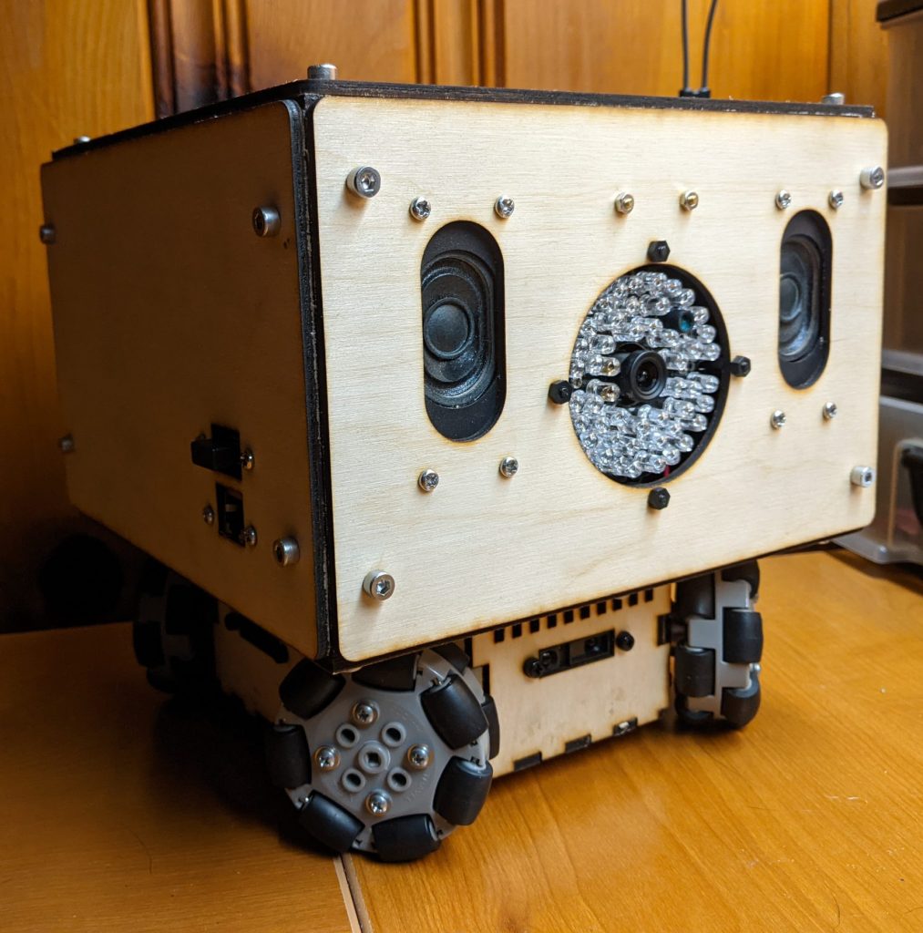
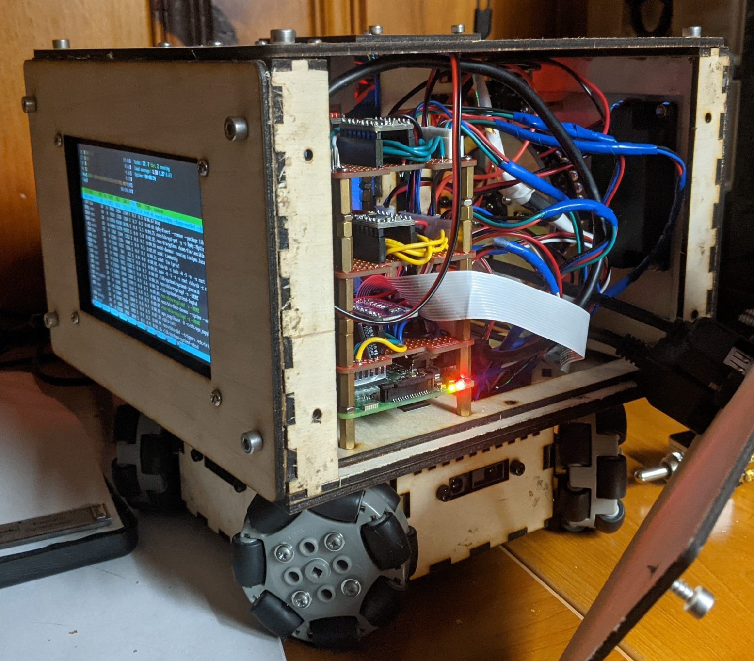
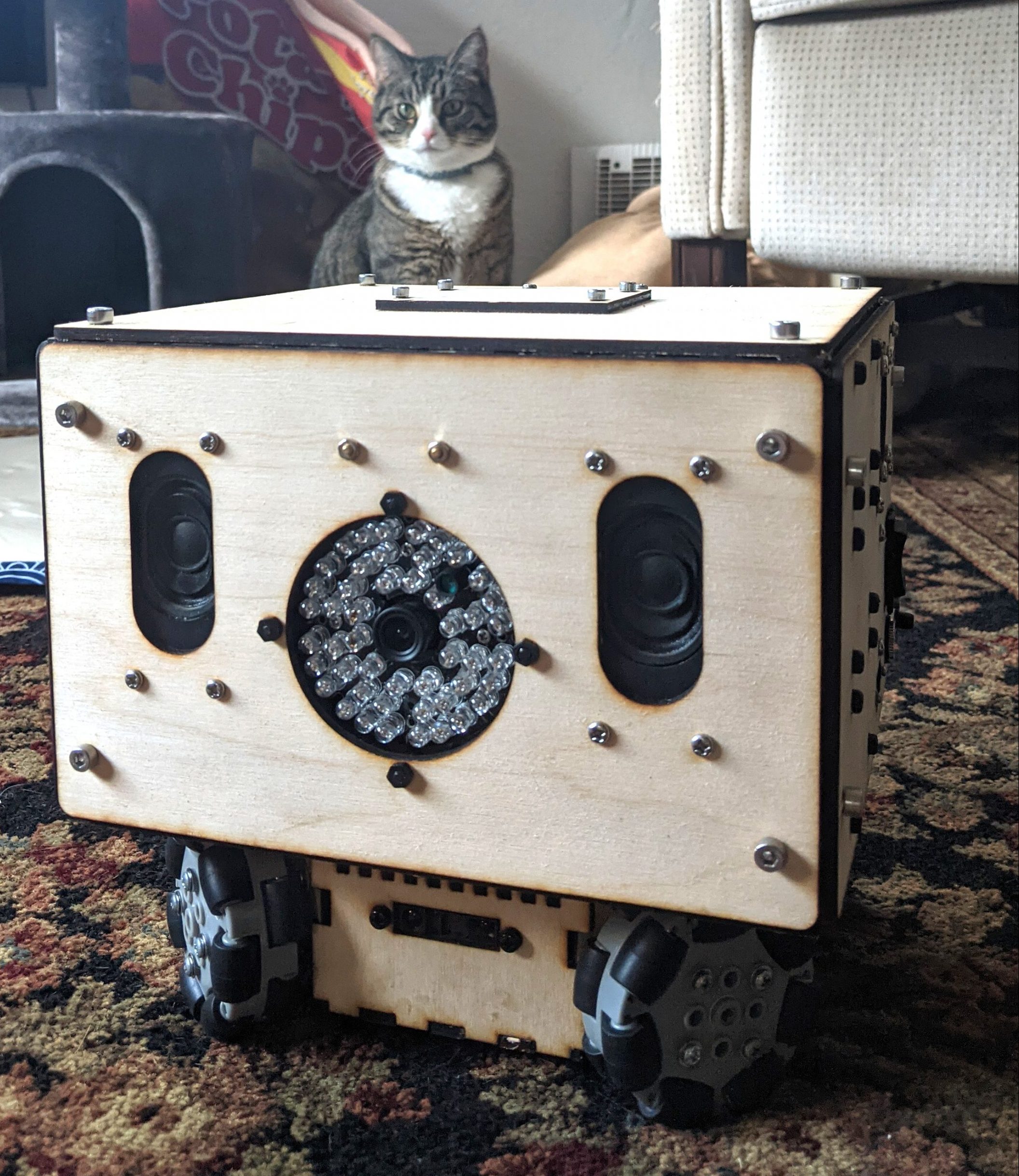
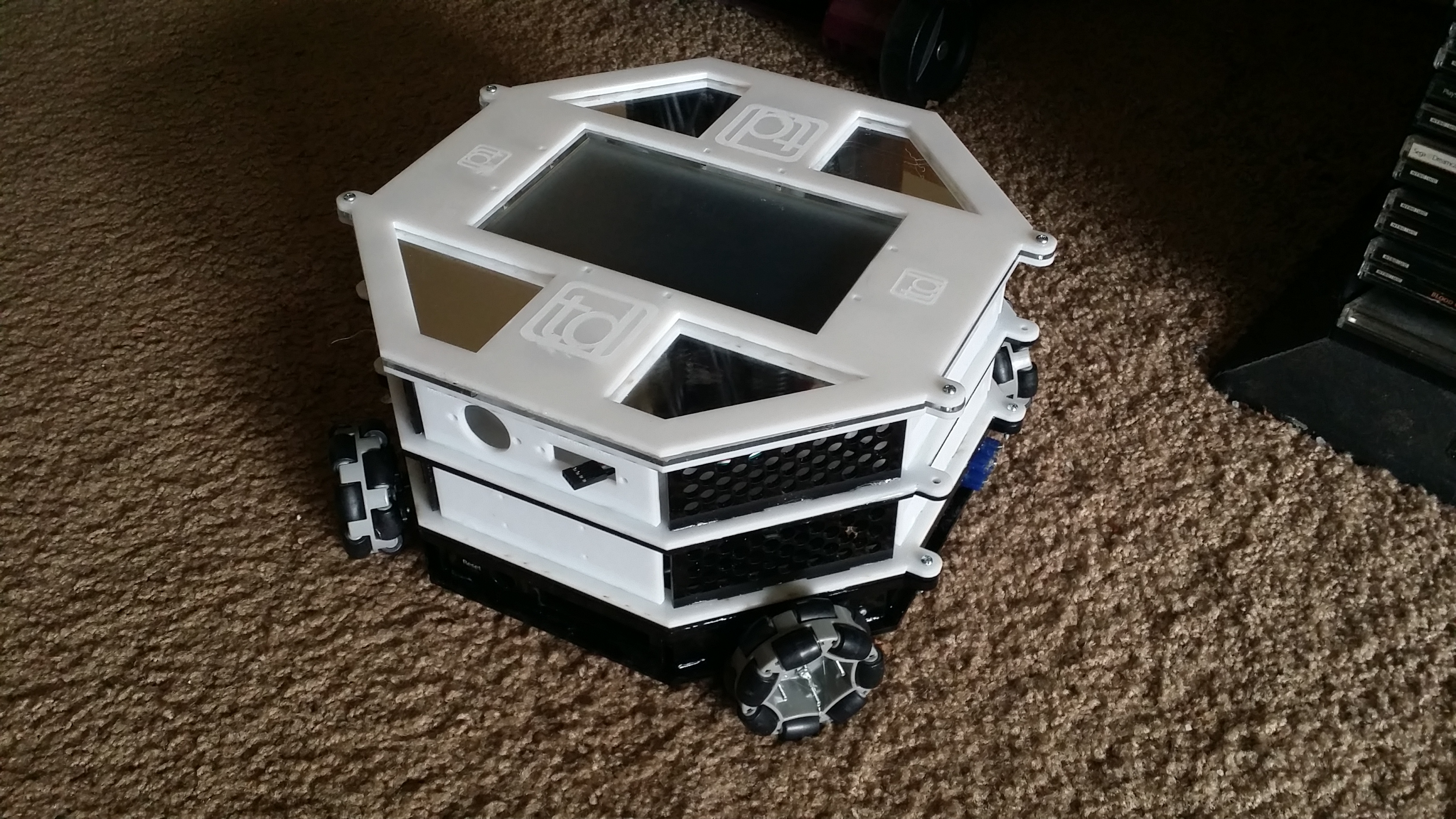
I’m proud to report that my newest robot iteration has been built. Look at it in all its glory:
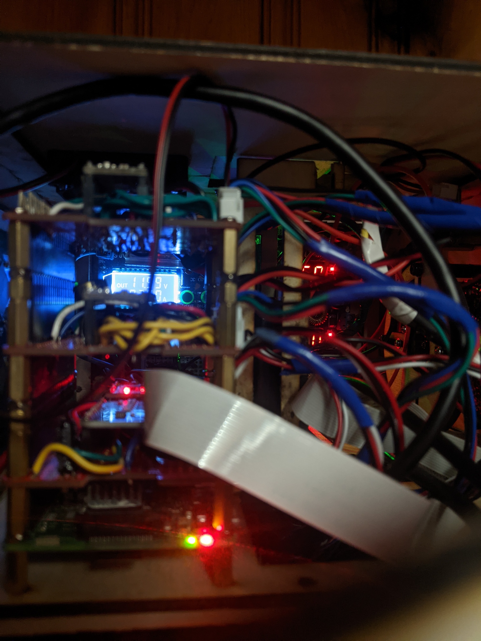
So far, all I’ve been able to verify that the basic system is working as intended. The LCD screen is working great. The power consumption is rather low at idle (assuming the IR illuminator isn’t triggered). The I2C bus is showing that the 4 channel ADC is working, as is the accelerometer. The camera is also working well.
Next Steps
Now that the basics are all verified as operational, it’s time to start testing things further.
Things Left To Test
Test the 4 channel ADC circuit
Test the accelerometer circuit
Test the stepper motors
Things Left To Implement
In short, everything needs to be implemented. In no particular order, here’s what I have planned for the next few weekends:
Write proof of concept code to read in the values from the ADC
Simple movement test program to have the robot perform a predetermined routine to test out the wheels
The movements, if done properly, should cause the robot to return to its original location
Use some sort of cat and kata pun in the name. pookata? catkata? catkatapoo?
Create a console (i.e. ncurses) based application to expose the robots internal state in a top like fashion
This will mainly be a great way for me to ssh in and screen -r to see what’s going on inside the robot.
It doesn’t have to be pretty, but it should be at least look as nice as htop or glances.
Should show the current acceleration state of all the motors, ranges finder values, and temperature
UI/UX mockups and design
For the range finders, I want something not precise but intuitive to understand. Maybe fade in red on the edges of the screen? Front side is the top of the screen, and so forth? As the range is shorted, fade in a red hue like an injury indicator from Black Ops Zombies? Visually it might read as “not having space” equals “robot pain”. I’m ok with that. Hell, lean into it. Make the robot attempt to always maximize the distance between it and everything else.
A configuration page would be necessary
This would mostly be related to configuring network settings on the fly away from home.
What differences would there be between the UI on the back of the robot, and what you’d see in the browser?
Should disallow changing system or network settings over mobile
Could display CPU utilization and not on mobile? I’d be ok with having as much debugging shown in the mobile app actually… something like out of old school Terminator movie vision.
Actually implement the mobile interface
I’d like to use ReactJS with the interface, as I’d like the option to port it to a mobile app later
Should work well on desktop and mobile
End Goal
The initial version will focus on allowing easy remote control via any web browser that can connect to its built-in Wifi hotspot. The user interface should be simple and intuitive. Within 5 seconds of loading the website, my wife should be able to use it to chase the cats around in the dark.
Once I’ve gotten that far, the sky’s the limit from there. I could start learning about AI, and pursue making the robot autonomous. I could instead focus on making it as small and energy efficient as possible. What about making them as cheap as possible, so that I could have a swarm? Lastly, I could instead focus on making it able to navigate outside or in water.
In whatever path I choose, I’ll be able to reuse large amounts of code and object models. I’m looking forward to that.
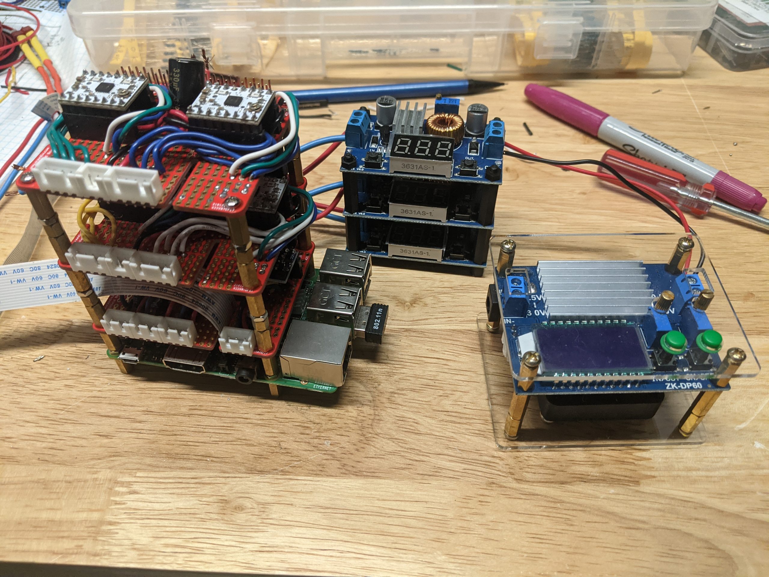
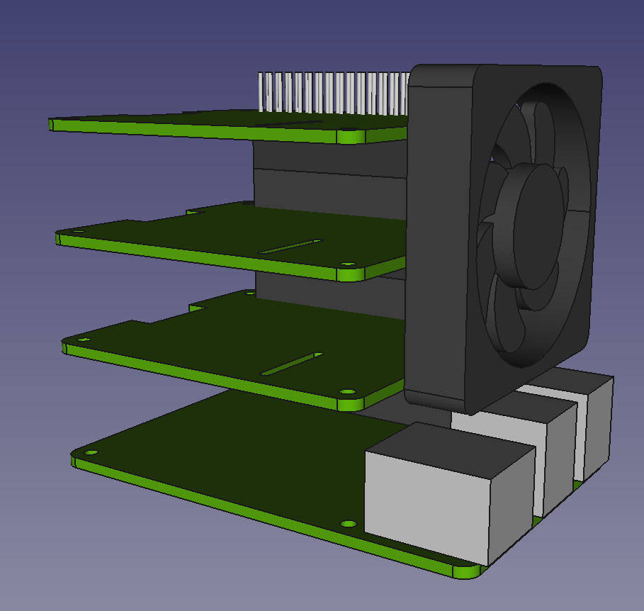
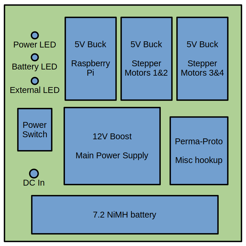
Way back when, I designed that I wanted to learn how to create a circuit board from scratch. It was fun and I learned a lot. Unfortunately, one of the things that I learned was it takes forever to build proper circuits. It also costs a lot. For someone like myself who’s learning, it’s best to simply use some permaproto style Raspberry Pi HATs. Using 20mm standoffs and doubling up some stacking headers gives me plenty of space.
While this isn’t very space efficient, it still would fit inside of 4″ cube which is small enough for my purposes.
Layer Overview
Raspberry Pi
Nothing special here
Leaning towards using the 20mm standoffs to allow more air flow over the CPU
Motors 1 and 2
Include at least 1 massive capacitor for the motors
An additional capacitor right where the power enters would be nice too
Motors 3 and 4
Don’t forget those capacitors
Sensors
4 channel ADC board with i2c interface for the range finders
Accelerometer with i2c interface
Build Notes
Check wiring twice, solder once
I ended up going with the solder trice, check nonce.
Hours were wasted, but I’ve become even more confident in my soldering skills
Getting the standoffs to match up with the stacked headers was a larger pain than anticipated.
Making the accelerometer circuit board perfectly level was impossible.
Some sort of calibration step will be necessary.
The range finders require 5v power but output in 3.3v logic.
This could’ve explained issues that I had in the past on the Arduino. I remember vaguely issues with not getting the range of values that I was expecting.
This strategy of doing outrageous RPi HATs works surprisingly well.
Doing the separate daughter board with the 40pin ribbon cable is actually more cumbersome than vertically stacking.
This obviously only works well where I can go high. A more flat, pancake shaped robot wouldn’t work.
I remember when I first started playing with robotics, I was always asked what my goals were. I never had a good answer for that. Here’s my thoughts on a better answer.
True Goals
The ultimate goal is to learn enough to consider a change of career. My ultimate dream would be to create affordable robotics kits for kids to built their own robots. I remember how much DJGPP and other free software projects helped me when I was starting out. Wouldn’t it be awesome to allow the next generation access to open source technology? Then I feel good for helping kids, while those kids can one day go on to create something more amazing than I could. Everyone wins.
To accomplish my goal, I’ve got vaguely defined constraints. Whatever I create shouldn’t cost more than $500 to recreate. I want to keep the price low enough that any parent can afford to give their kid(s) the tools necessary to learn the fundamentals. With economy of scale, I should be able to get that down to $100 if my idea pans out.
Functionality Related Goals
Must have a web based UI that works with any browser
Must be able to see in the dark
Must use omnidirectional wheels for a holonomic drive
Power input must be flexible as possible
Should be lit up like a Christmas Tree
Remote Control
I’m a web developer, so the UI will definitely be web based
I’ve enjoyed using Bootsrap for years, so that’s definitely going in there
Video should take up as much of the view as possible
Putting the controls on top of the video worked in the past
Vision
It must be able to see a black cat in pitch black darkness
I’ve had trouble with getting low latency and good frame rates in the past
Resolution doesn’t need to be very high, but should be at least as good as DVD (480p)
The illuminator I have works okay with the all the NoIR cameras I’ve bought
Holonomic Drive
I’m vacillating between 3 and 4 wheels
No matter what, still have 4 total stepper drivers wired up.
IR illuminator must be effective at least 3 meters away from the robot
Power
Getting at the battery was always annoying in previous designs, so make it easy to swap out batteries
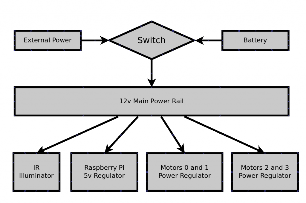
Using a beefy SPDT switch to allow switching quickly between internal and external worked really well in the past
Don’t worry about designing any advanced charging circuitry
Christmas Tree Aesthetics
Case should be as clear as possible to allow as much light out as possible
Engraving designs into the plexiglass might be a fun idea
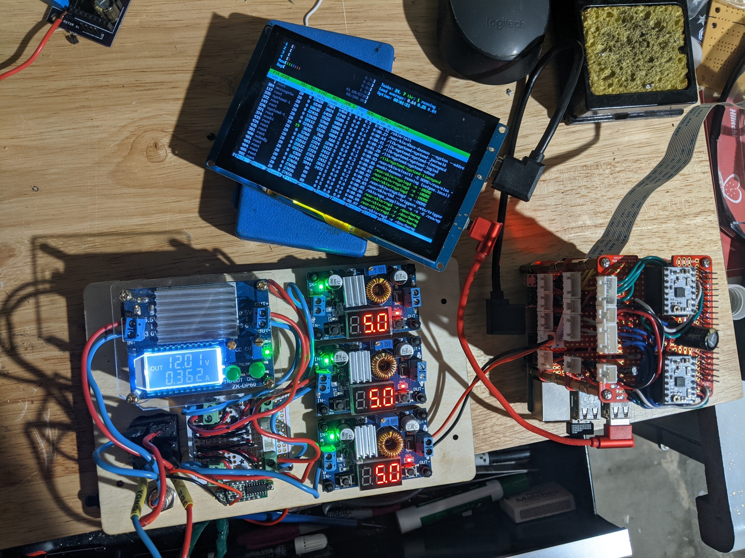
The 5″ touchscreen should be used for displaying as much internal information as possible
Use power regulators with displays showing voltage will be helpful
It’s about time I ruminate on power issues I’ve had in the past. In previous iterations, I cut a lot of corners with the power. Melted wires and malfunctioning steppers were the main issues I remembered facing. This brain dump will be help to avoid all the power issues in this next, final holonomic robot.
Past Power Problems
Previous designs considered power supply as an afterthought
Running all stepper motors off a single power supply proved problematic
The amount of current passing through would often surpass what the power supply was capable of
Microstepping would fail or become unreliable due to voltage irregularities
Even regular steps would cause problems
If I needed 1A max for a load, then I’d only have 1A max available
Designing power circuitry like I worked for Apple was a bad idea, as all that does is lead to overheating
Sometimes wires would melt or components would release the magic smoke from within
What’s Worked in the Past
Using a beefy SPDT switch to allow powering the robot externally or from battery proved helpful
Keeping the external and internal power physically separated avoided a lot of potential issues
It was very simple to troubleshoot power input issues as things were very simple
The battery should be easy to access and replace
At minimum, it should be easy to recharge.
Physically replacing it easily is a nice to have, especially when I show up with multiple fully-charged batteries
Strategies and Mitigation Plans for the Future
Have one single 12v main power rail that everything else connects to
Going overkill on the main rail will leave me with more power than I know what to do with
I don’t want to have to remove functionality again due to lack of current
This will allow me to scale the robot up to whatever size I would like
From the main 12v rail, I’ll use a series of buck converters to get the proper voltage(s) required
Build and be prepared to handle lots of current (12V * 5A = 60W)
Once I get good, I can drop the power requirements.
Until then, assume the following padded numbers:
5V × 5A for Raspberry Pi and peripherals
4 motors * 2 coils/motor * (2.7V * 1A) for the motors
5V * 1A padding for feature creep
Total power at worst: (5V*5A) + 4 * (2*2.7V*1A) + (5V * 1A) = 52W
My best guess of average power would be more like 35W
On battery power, it’s looking like I’ll be discharging around 1 to 2C maximum. I can’t find power ratings for the batteries that I have, but it’s looking like a lot of comparable ones are 25C, 50C or even higher.
Note: This post is a work-in-progress and will be updated as requirements are fully fleshed out.
Way back when I started playing around with robotics and electronics years ago, the most important thing to me was having a good name for my robotics projects. I came up with Cat Antagonizing Tactical Platform Of Oppression (or CATPOO for short). With the hardest part done, I remembered following the KISS principle. Within a week, I had a working remote controlled robot. It had a wireless access point with a web based UI with streaming video from the robot’s perspective. It just worked, and was compatible with every phone and laptop thrown at it.
However, aesthetically it was a mess. Ever since then, I’ve been running into situations where I’ve gone way into the weeds chasing a particular look without any concern for functionality. I’ve finally become fed up with spending tons of time creating robots that look great, but are difficult to work on. I’m tired of having to spend 45 minutes tearing it down to swap out of a single part, or check a single solder point.
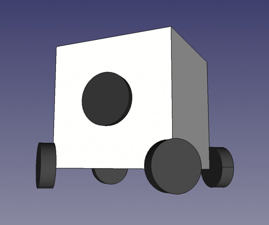
We’re going way back to my original design: a cube with 4 wheels. Once I get everything working well, then and only then, will I begin to care about aesthetics again.
Continued Reading
I was originally going to have one long and lengthy post about my goals, but decided it’d be easier for me to break up into smaller chunks. I’ll be adding to the following list as I continue fleshing out the project.
I’ve spent months planning my next CATPOO and it’s all printed out. All requisite parts are either here or on their way in the mail.
Highlights include:
Omnidirectional wheels for holonomic goodness
Infrared night vision camera
16x High intensity IR LEDs
7″ LCD with touchscreen
External USB and network ports
Wireless AP support
Rear motion sensor for Spidey Sense
Forward and rear proximity sensors
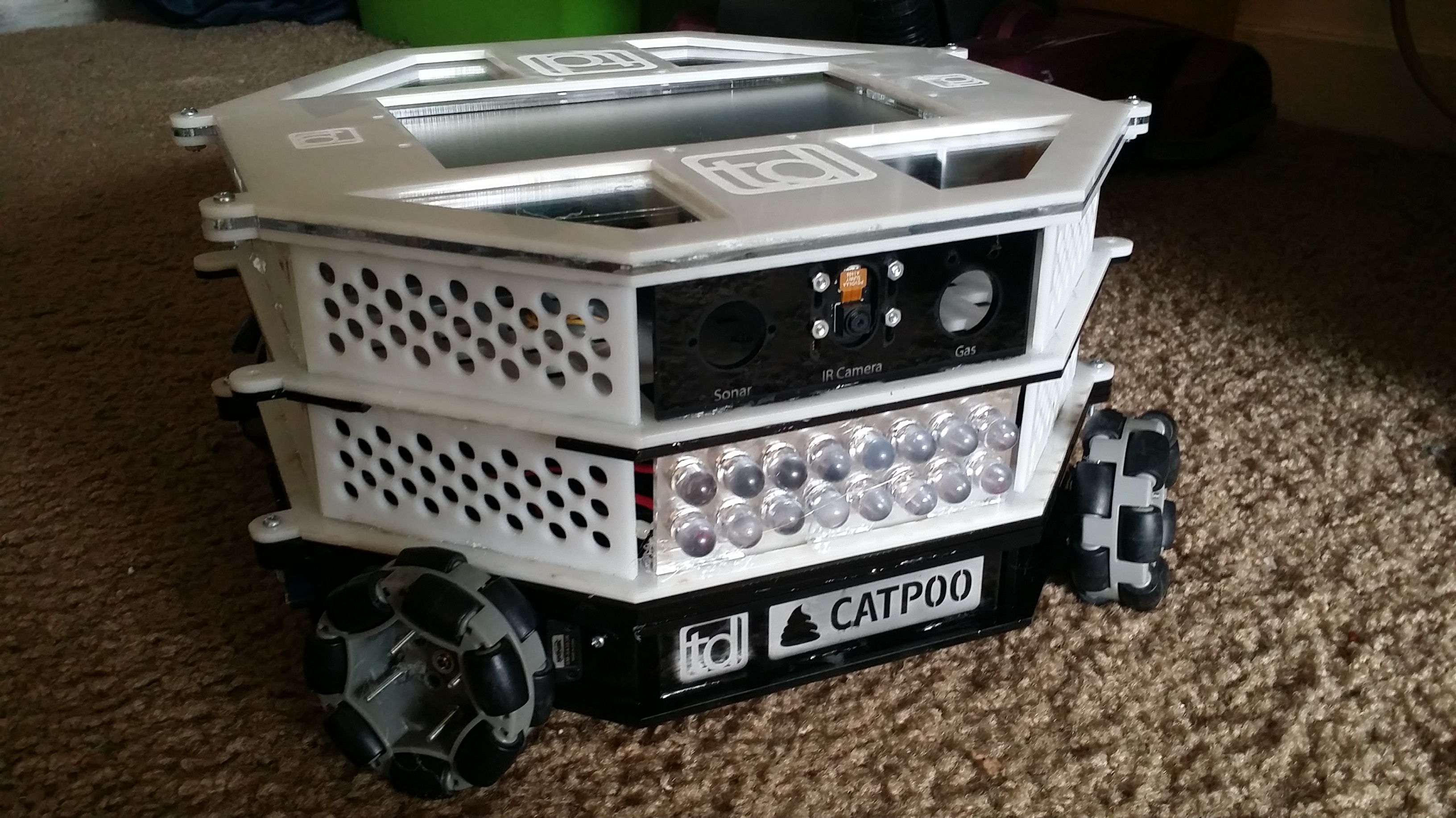
Front view showing IR LEDs and camera
Once I get the few minor parts remaining from Pololu, I’ll be ready done with the building in a day. If you think you might need it, and it’s only a $1 or $2, just get it. Waiting three days to finish the build because I’m short on 1″ #4 screws is a terrible experience.
Once built, I’m nervous when it comes to figuring out how to coordinate all four servos to move in a straight line. Previously, I ran into trouble with getting the forward and reverse speeds to be equal. It could also be related to the servos I’m using. I plan to isolate whether it’s my fault, the motors’ faults, or a combination of both. I’ll have eight servos soon.
If I can’t get four functional servos out of that, I’m smashing the servo controller I have a sledgehammer and switching to stepper motors. I didn’t want to spend the money or effort, but it’s looking like that’s the direction I’ll be going.
Finally! After over a year off and on, I finally have all the parts and necessary free time available.
Milestone Highlights
The basic robot is now working with the two servos to maneuver with
The night vision camera is working (at about half the full brightness)
Video lag to web UI on a smartphone is less than one second in bright areas, twice as long in dark (due to exposure times delaying transmitting next frame)
Next Up
Add in more sensors (highest priority is the proximity sensor for the front)
5″ LCD screen for the top for debugging and status output
Integrate the momentary switches with built-in LEDs to perform operations (ex: reset networking, turn on/off IR lights, etc.)